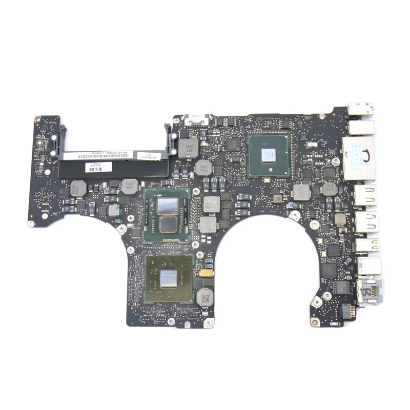
- #A1286 LOGIC BOARD LCD CONNECT HOW TO#
- #A1286 LOGIC BOARD LCD CONNECT CODE#
- #A1286 LOGIC BOARD LCD CONNECT SERIES#
When using a 20×4 LCD change this line to lcd.STM32 development board, STM32F407IGT6, USB HS/FS, Ethernet, NandFlash, JTAG/SWD, LCD, USB TO UART Overview EVK407I is an STM32 development board which consists of a mother board and a MCU core board XCore407I. In the setup() the LCD is initiated with the function begin(cols,rows). You will need to change ‘lcd’ to the new name in the rest of the sketch. You can give it a different name if you want like ‘menu_display’. Note that we have called the display ‘lcd’. As parameters we use the Arduino pins to which we connected the display.

The is done with the function LiquidCrystal(rs, enable, d4, d5, d6, d7). You should see the following output on the LCD:Īfter including the library, the next step is to create a new instance of the LiquidCrystal class. Set the cursor on the third column and the second row: Set the cursor on the third column and the first row, counting starts at 0: Specify the LCD's number of columns and rows. LiquidCrystal lcd = LiquidCrystal(2, 3, 4, 5, 6, 7)
#A1286 LOGIC BOARD LCD CONNECT CODE#
* Basic Arduino example code for displaying text on 16x2, 20x4 etc. Next, I will show you how the code works and how you can use the other functions of the LiquidCrystal library.
#A1286 LOGIC BOARD LCD CONNECT HOW TO#
The example code below shows you how to display a message on the LCD. The LiquidCrystal library comes with many built-in functions and makes controlling character LCDs super easy. You can check the datasheet for the maximum current rating of the backlight and use this to select an appropriate resistor value. If your display doesn’t include a resistor, you will need to add one between 5 V and pin 15. It should be safe to use a 220Ω resistor, but this value might make your display a bit dim.

You should find it on the back of the LCD connected to pin 15 (Anode).
#A1286 LOGIC BOARD LCD CONNECT SERIES#
Most LCDs have a built-in series resistor for the LED backlight. In order to test the display, you will need to make the connections as shown in the figure below. You will only need to change the size specifications in your Arduino code. These LCDs are available in many different sizes (16×2 1602, 20×4 2004, 16×1 etc.), but they all use the same HD44780 parallel interface LCD controller chip from Hitachi. is a participant in the Amazon Services LLC Associates Program, an affiliate advertising program designed to provide a means for sites to earn advertising fees by advertising and linking to products on.

Check out the tutorial below if you want to use an I2C module as well: Recommended tutorials: With this I2C module, you only need two connections to control the LCD. I therefore like to use them with an I2C interface module mounted on the back.

As you will see, you need quite a lot of connections to control these displays.


 0 kommentar(er)
